
Product Overview
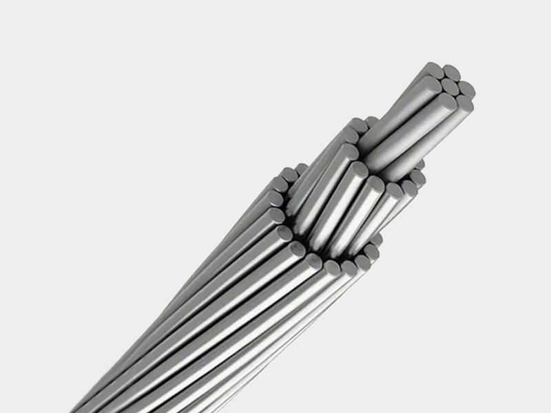
ACAR — Aluminum Conductor Alloy Reinforced (IEC 61089, A1/A3) is a concentric-lay stranded bare overhead conductor produced to IEC 61089, combining Class A1 aluminium wires (1350-H19, 61% IACS) with a Class A3 aluminium-magnesium-silicon alloy core. In the IEC 61089 classification system, Class A3 refers to AlMgSi alloy wire in the artificially aged and strain-hardened temper — a higher-strength alloy designation compared to Class A2, optimised for applications requiring maximum tensile performance from the alloy component. The A3 alloy core provides a stranded central reinforcement of high-tensile AlMgSi wires around which one or more layers of A1 aluminium strands are concentrically wound.
The structural distinction from A1/A2 ACAR is in the alloy core arrangement: A1/A3 ACAR typically features a defined alloy core (the A3 wires concentrated in the centre layers) surrounded by A1 aluminium outer layers — analogous in concept to ACSR's core/shell arrangement but using a single-metal-family all-aluminium construction. This core-shell geometry concentrates the high-strength A3 alloy where it contributes most efficiently to tensile load-carrying, while the outer A1 aluminium layers maximise the conductor's surface area and current-carrying cross-section. The result is a conductor that achieves a higher tensile efficiency (strength per unit cross-section) than A1/A2 designs of the same total area. Available from 16 mm² to 1400 mm², with dual stranding configurations for most sizes above 250 mm².
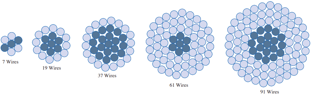
A1 Outer Layers — 1350-H19 aluminium (61% IACS), carries the bulk of the electrical current
A3 Core Wires — AlMgSi alloy (higher tensile strength than A2), concentrated in core layers for tensile efficiency
Same Wire Diameter — A1 and A3 wires are identical in diameter; adjacent layers wound in opposite directions
No Steel — All-aluminium family, no bimetallic interface or galvanic corrosion risk
A3 Alloy Core — Higher Tensile Efficiency
Class A3 AlMgSi alloy in the artificially aged + strain-hardened temper achieves higher tensile strength than Class A2 of the same composition. Concentrating A3 wires in the core layers maximises their contribution to tensile load-carrying — delivering higher breaking load per unit of alloy cross-section than uniformly distributed A1/A2 designs.
Core-Shell Architecture
A3 alloy wires form the core; A1 aluminium wires form the outer layers. This separates function by position: the core carries tension (requiring strength), the outer layers carry current (requiring conductivity). The architecture mirrors ACSR's engineering logic while remaining all-aluminium and free of galvanic corrosion.
No Steel Core — No Galvanic Corrosion
All-aluminium-family construction eliminates the bimetallic galvanic corrosion mechanism that is the primary long-term failure mode of ACSR in coastal, tropical, and industrially polluted environments — delivering ACSR-comparable tensile strength with superior 40+ year corrosion reliability.
IEC 61089 Global Acceptance
IEC 61089 A1/A3 designation is specified and accepted by utilities across Europe, Africa, the Middle East, and Asia for overhead line procurement — integrating directly into IEC-standard project documentation and tender specifications.
Dual Configuration Key Sizes
Most cross-sections above 250 mm² are available in two stranding configurations — a higher A3-ratio option (greater tensile strength, lower resistance, suitable for long spans) and a higher A1-ratio option (greater conductivity, suitable for shorter spans and urban distribution) — specifiable at order.
16–1400 mm² Range
35 standard configurations from 16 mm² to 1400 mm² cover the full IEC overhead conductor cross-section range — from rural LV distribution through MV/HV distribution to high-capacity sub-transmission and transmission applications.
Technical Specifications
Basic Parameters
| Standard | IEC 61089 — Round wire concentric lay overhead electrical stranded conductors |
|---|---|
| IEC Material Designation | A1/A3 — Class A1 (1350-H19, 61% IACS) + Class A3 (AlMgSi alloy, higher-strength temper) |
| A1 Wire (1350-H19) | Hard-drawn aluminium, 61% IACS, tensile strength 160–175 MPa — outer layers |
| A3 Wire (AlMgSi) | Aluminium-magnesium-silicon alloy, artificially aged + strain-hardened; higher tensile strength than A2 — core layers |
| Wire Diameter Rule | All A1 and A3 wires have the same nominal diameter within a given conductor size |
| Construction | Core-shell: A3 alloy wires form core layers; A1 aluminium wires form outer layers; adjacent layers in alternating lay directions |
| Size Range | 16 mm² to 1400 mm² — 35 standard configurations |
| Max. Continuous Temperature | 75 °C (A1 component limit) / 90 °C (A3 component limit) |
| Surface Finish | Bare; grease-filled available on request |
| Packaging | Wooden or steel drum; 500 m / 1000 m standard; custom lengths available |
Full Parameter Table — IEC 61089 ACAR A1/A3 (16–1400 mm²)
| Code Number (mm²) | A3 Alloy Area (mm²) | A1 Al Area (mm²) | A3 Stranding (No./mm) | A1 Stranding (No./mm) | Overall Ø (mm) | Weight (kg/km) | DC Resistance (Ω/km, 20°C) |
|---|---|---|---|---|---|---|---|
| 16 | 9.78 | 7.33 | 4/1.76 | 3/1.76 | 5.29 | 46.8 | 1.7896 |
| 25 | 15.3 | 11.5 | 4/2.21 | 3/2.21 | 6.62 | 73.1 | 1.1453 |
| 40 | 24.4 | 18.3 | 4/2.79 | 3/2.79 | 8.37 | 117.0 | 0.7158 |
| 63 | 38.5 | 28.9 | 4/3.50 | 3/3.50 | 10.5 | 184.3 | 0.4545 |
| 100 | 61.1 | 45.8 | 4/4.41 | 3/4.41 | 13.2 | 292.5 | 0.2863 |
| 125 | 83.7 | 48.8 | 12/2.98 | 7/2.98 | 14.9 | 364.1 | 0.2302 |
| 160 | 107 | 62.5 | 12/3.37 | 7/3.37 | 16.9 | 466.0 | 0.1798 |
| 200 | 134 | 78.1 | 12/3.77 | 7/3.77 | 18.8 | 582.5 | 0.1439 |
| 250 | 167 | 97.6 | 12/4.21 | 7/4.21 | 21.1 | 728.1 | 0.1151 |
| 250 | 132 | 139 | 18/3.05 | 19/3.05 | 21.4 | 746.0 | 0.1154 |
| 315 | 263 | 61.4 | 30/3.34 | 7/3.34 | 23.4 | 894.4 | 0.0916 |
| 315 | 166 | 175 | 18/3.43 | 19/3.43 | 24.0 | 940.0 | 0.0916 |
| 400 | 334 | 78.0 | 30/3.77 | 7/3.77 | 26.4 | 1135.8 | 0.0721 |
| 400 | 211 | 222 | 18/3.86 | 19/3.86 | 27.0 | 1193.7 | 0.0721 |
| 450 | 376 | 87.7 | 30/3.99 | 7/3.99 | 28.0 | 1277.8 | 0.0641 |
| 450 | 237 | 250 | 18/4.10 | 19/4.10 | 28.7 | 1342.9 | 0.0641 |
| 500 | 418 | 97.5 | 30/4.21 | 7/4.21 | 29.5 | 1419.8 | 0.0577 |
| 500 | 263 | 278 | 18/4.32 | 19/4.32 | 30.2 | 1492.1 | 0.0577 |
| 560 | 468 | 109 | 30/4.46 | 7/4.46 | 31.2 | 1590.1 | 0.0515 |
| 560 | 505 | 65.5 | 54/3.45 | 7/3.45 | 31.1 | 1573.9 | 0.0516 |
| 630 | 456 | 206 | 42/3.72 | 19/3.72 | 33.4 | 1826.0 | 0.0458 |
| 630 | 272 | 420 | 24/3.80 | 37/3.80 | 34.2 | 1909.0 | 0.0458 |
| 710 | 514 | 232 | 42/3.95 | 19/3.95 | 35.5 | 2057.8 | 0.0407 |
| 710 | 307 | 473 | 24/4.03 | 37/4.03 | 36.3 | 2151.4 | 0.0407 |
| 800 | 579 | 262 | 42/4.19 | 19/4.19 | 37.7 | 2318.7 | 0.0361 |
| 800 | 346 | 533 | 24/4.28 | 37/4.28 | 38.5 | 2424.2 | 0.0361 |
| 900 | 651 | 294 | 42/4.44 | 19/4.44 | 40.0 | 2608.5 | 0.0321 |
| 900 | 569 | 390 | 54/3.66 | 37/3.66 | 40.3 | 2649.5 | 0.0321 |
| 1000 | 818 | 216 | 72/3.80 | 19/3.80 | 41.8 | 2855.4 | 0.0289 |
| 1000 | 632 | 433 | 54/3.86 | 37/3.86 | 42.5 | 2943.9 | 0.0289 |
| 1120 | 916 | 242 | 72/4.02 | 19/4.02 | 44.3 | 3198.1 | 0.0258 |
| 1120 | 708 | 485 | 54/4.09 | 37/4.09 | 45.0 | 3297.2 | 0.0258 |
| 1250 | 1022 | 270 | 72/4.25 | 19/4.25 | 46.8 | 3569.3 | 0.0231 |
| 1250 | 791 | 542 | 54/4.32 | 37/4.32 | 47.5 | 3679.9 | 0.0231 |
| 1400 | 1145 | 302 | 72/4.50 | 19/4.50 | 49.5 | 3997.6 | 0.0207 |
A1/A3 vs A1/A2 — IEC ACAR Alloy Designation Clarification
| Parameter | IEC 61089 A1/A3 (this product) | IEC 61089 A1/A2 |
|---|---|---|
| A1 wire | 1350-H19 aluminium (61% IACS) — identical | 1350-H19 aluminium (61% IACS) — identical |
| Reinforcing alloy wire | Class A3 — AlMgSi, artificially aged + strain hardened; higher temper | Class A2 — AlMgSi / 6201-T81; standard temper |
| Alloy tensile strength | Higher (A3 temper) | Moderate (~315 MPa, A2/6201-T81) |
| Alloy conductivity | Slightly lower than A2 (higher alloy content) | 52.5% IACS (6201-T81) |
| Core arrangement | A3 wires concentrated in core layers | A2 wires may be distributed throughout or in core |
| Best for | Long spans, maximum tensile demand, river crossings | Balanced conductivity/strength, medium-long spans |
| Wire diameter rule | All wires same diameter | All wires same diameter |
| Size range | 16–1400 mm² (35 configurations) | 16–1400 mm² (35 configurations) |
Key Features & Technical Advantages
Maximum Tensile Efficiency — A3 Core
Concentrating the higher-strength A3 alloy wires in the core layers maximises their mechanical contribution — the core carries the greatest tensile load in a stranded conductor. This core-shell architecture achieves higher breaking load per unit of alloy cross-section than uniformly distributed A1/A2 designs of the same total cross-section.
Higher Strength Than A1/A2 for Same Cross-Section
The A3 temper delivers higher tensile strength than A2 (6201-T81) from the same AlMgSi alloy family. For a given conductor cross-section and stranding configuration, A1/A3 ACAR achieves higher rated breaking load than A1/A2 ACAR — enabling longer spans or higher mechanical loading on the same total conductor area.
No Steel Core — Corrosion Resistance
All-aluminium-family construction eliminates galvanic corrosion at the aluminium-steel interface — the primary long-term failure mechanism of ACSR in coastal, tropical, and industrial environments. A1/A3 ACAR delivers maximum tensile strength without steel, preserving 40+ year outdoor service life in the harshest overhead line environments.
Lighter Than ACSR for Equal Tensile Strength
A3 alloy wires contribute mechanical strength at aluminium density (2.70 g/cm³) versus steel's 7.85 g/cm³. For equivalent breaking load, A1/A3 ACAR is significantly lighter than ACSR, reducing dead load on towers, wind/ice loading, and foundation requirements across all conductor sizes.
IEC 61089 — Global Utility Acceptance
IEC 61089 A1/A3 is accepted by utilities across Europe, Africa, the Middle East, and Asia. The mm² cross-section designation and IEC material class notation integrate directly into IEC-standard procurement documentation and engineering specifications.
Greased Core Option Available
Greased A3 core variant available for marine, industrial pollution, and high-humidity environments — the grease fills the interstices of the alloy core wires, blocking moisture ingress and preventing the inter-strand fretting corrosion that can develop on long-service ACAR conductors in severely wet environments.
Certifications & Standards
Typical Applications
River & Long-Span Crossings
The primary A1/A3 advantage over A1/A2 — maximum tensile strength for the longest spans where ACSR-class breaking load is required without a steel core.
HV & EHV Transmission Lines
Large A1/A3 ACAR (630–1400 mm²) for 132–500 kV transmission in IEC markets where high capacity and no-steel corrosion resistance are both specified.
Coastal & Marine Overhead Lines
High-strength A1/A3 preferred over ACSR wherever salt air and humidity make galvanic core corrosion a design-life risk — maintaining both tensile performance and corrosion reliability over 40+ years.
Mountain & High-Wind Terrain
Lines through exposed mountain terrain with high wind loading and long spans — A1/A3's higher breaking load allows larger span-to-sag ratios and fewer tower foundations in difficult ground.
Industrial & Chemical Zone Lines
Overhead supply through corrosive industrial atmospheres — all-aluminium construction immune to the galvanic corrosion mechanism that degrades ACSR in chemically contaminated environments.
Tropical IEC Markets
Sub-Saharan Africa, South Asia, and Southeast Asia IEC grid projects where long spans, high humidity, and no-steel corrosion requirements converge — A1/A3 satisfies all three simultaneously.
ACSR Reconductoring
Direct replacement of corroded ACSR on coastal and tropical IEC overhead lines — A1/A3 ACAR matches or exceeds ACSR breaking load with all-aluminium corrosion resistance, compatible with IEC hardware and fittings.
Urban Sub-Transmission
Medium A1/A3 (315–630 mm²) for 33–132 kV sub-transmission where longer span capability reduces pole count in congested urban rights-of-way and underground duct requirements.