
Product Overview
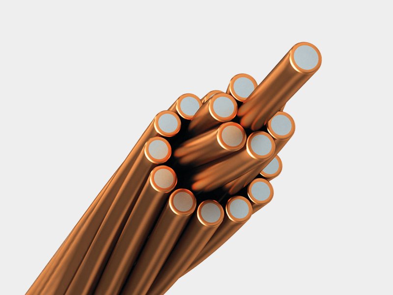
CCS — Copper Clad Steel Conductor (ASTM Standard) is manufactured to ASTM B227 (Hard-Drawn Copper-Clad Steel Wire), ASTM B228 (Concentric-Lay-Stranded Copper-Clad Steel Conductors), and ASTM B910 (Annealed Copper-Clad Steel Wire) — the definitive North American specifications for CCS wire and strand. The conductor combines a high-tensile steel core with a continuous metallurgically bonded copper outer layer, delivering the conductivity of copper and the mechanical strength of steel in a single composite wire.
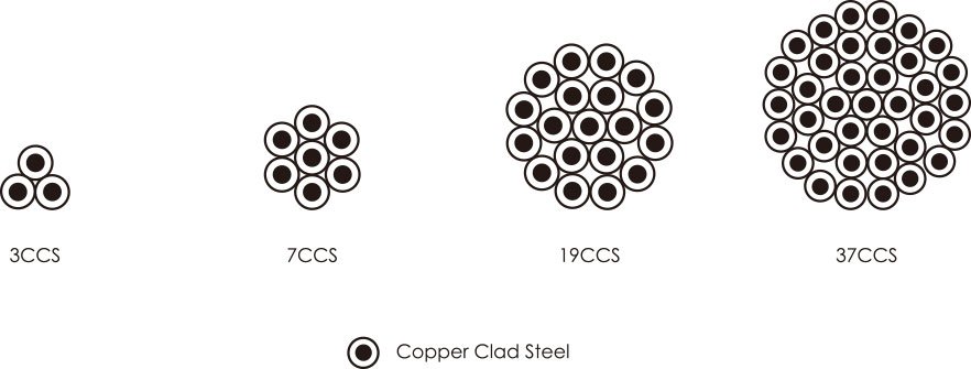
ASTM CCS conductors are designated by AWG wire size and available in solid (1-wire), 3-wire, 7-wire, and 19-wire stranded constructions in two conductivity grades: 30% IACS (thinner copper layer, higher steel fraction, higher tensile strength) and 40% IACS (thicker copper layer, better conductivity, lower tensile strength). The ASTM data tables include I²t values (thermal withstand capacity) and short-time fusing current (30-cycle fault current that causes conductor fusing) — critical design data for grounding and earth wire fault current duty not available in the IEC tables.
Copper Outer Layer — 40% IACS (thick cladding) or 30% IACS (thin cladding); metallurgical bond
Steel Core — High-carbon hard-drawn steel; provides tensile strength
ASTM B227/B228 — Hard-drawn temper (standard); ASTM B910 — Annealed temper (flexible)
AWG Sizing — No. 2 solid through 19-wire 19 AWG stranded constructions
ASTM B227 / B228 / B910 Compliance
Full compliance with North American CCS wire and strand standards — accepted by US and Canadian utilities for overhead earth wire, buried grounding grid, and messenger wire applications under NEC, NESC, and utility project specifications.
I²t & Fault Current Data
ASTM CCS tables include I²t (kA²s) values and 30-cycle short-time fusing current (kA) — engineering data essential for sizing grounding conductors to withstand system fault current without fusing during protective relay clearance time. Not available in IEC CCS tables.
AWG Size Series
Sizes from No. 12 AWG (3-wire) through 19 No. 5 AWG (19-wire) cover the full range of North American grounding conductor and overhead earth wire applications — directly compatible with AWG-specified project drawings and NEC grounding conductor sizing tables.
30% & 40% IACS — Two Grades
30% IACS grade: higher tensile strength, higher resistance — for overhead shield wire and long-span earth wire where mechanical strength dominates. 40% IACS grade: better conductivity, lower resistance — for buried grounding grid and neutral conductors where fault current capacity is the design driver.
Theft Deterrent
CCS has no recoverable copper scrap value and resists cutting with standard wire cutting tools. CCS grounding grids and overhead earth wires remain in service in regions where bare copper is repeatedly stolen — eliminating recurring replacement cost and infrastructure downtime.
Metallurgical Bond — No Delamination
Copper cladding is drawn simultaneously with the steel core, creating a true metallurgical bond — not a plated or coated surface. The copper layer cannot separate in service regardless of bending, mechanical stress, or fault current thermal cycling.
Technical Specifications
Basic Parameters
| Standards | ASTM B227 (Hard-Drawn CCS Wire); ASTM B228 (Stranded CCS); ASTM B910 (Annealed CCS Wire); ASTM B193 (Resistivity Test) |
|---|---|
| Conductivity Grades | 30% IACS (30HS — thinner copper, higher tensile strength); 40% IACS (40% — thicker copper, better conductivity) |
| Conductor Material | High-carbon steel core with metallurgically bonded copper outer layer |
| Temper | Hard-drawn (ASTM B227/B228, standard); Annealed (ASTM B910, on request) |
| Construction | Solid (1-wire); 3-wire stranded; 7-wire stranded; 19-wire stranded |
| AWG Size Range | No. 12 AWG (3-wire) to No. 5 AWG (19-wire); solid No. 2, 4, 6 AWG |
| Resistance Reference Temp. | 68°F (20°C) |
| Resistance Unit | Ω/KFT (ohms per 1000 feet); multiply by 3.281 to convert to Ω/km |
| Breaking Load Unit | lbf and kN both provided |
| I²t Unit | kA²s (kiloampere-squared seconds) — thermal withstand for fault current rating |
| Packaging | Reel or drum; standard lengths to order; custom lengths available |
Parameter Table 1 — 30% IACS (30HS) CCS Conductor
| Strands | AWG | Overall Ø (in.) | Overall Ø (mm) | Breaking Load (lbf) | Breaking Load (kN) | Weight (lbs/kft) | Weight (kg/km) | Area (cmil) | Area (mm²) | I²t (kA²s) | Fusing Current 30cy (kA) | DC Resistance (Ω/KFT) |
|---|---|---|---|---|---|---|---|---|---|---|---|---|
| 1 | 2 | 0.258 | 6.54 | 2276 | 10.10 | 184.1 | 274.0 | 66368 | 33.63 | 30.26 | 7.78 | 0.5209 |
| 1 | 4 | 0.204 | 5.19 | 1431 | 6.40 | 115.8 | 172.3 | 41738 | 21.15 | 11.97 | 4.89 | 0.8283 |
| 1 | 6 | 0.162 | 4.12 | 900 | 4.00 | 72.8 | 108.4 | 26250 | 13.30 | 4.73 | 3.08 | 1.3169 |
| 3 | 4 | 0.440 | 11.18 | 4079 | 18.10 | 350.2 | 521.2 | 125215 | 63.45 | 107.73 | 14.68 | 0.2761 |
| 3 | 5 | 0.392 | 9.96 | 3234 | 14.40 | 277.6 | 413.2 | 99263 | 50.30 | 67.70 | 11.64 | 0.3483 |
| 3 | 6 | 0.349 | 8.87 | 2565 | 11.40 | 220.2 | 327.7 | 78732 | 39.89 | 42.59 | 9.23 | 0.4391 |
| 3 | 7 | 0.311 | 7.90 | 2035 | 9.10 | 174.7 | 260.0 | 62467 | 31.65 | 26.81 | 7.32 | 0.5534 |
| 3 | 8 | 0.277 | 7.03 | 1614 | 7.20 | 138.5 | 206.2 | 49537 | 25.10 | 16.86 | 5.81 | 0.6979 |
| 3 | 9 | 0.247 | 6.26 | 1279 | 5.70 | 109.8 | 163.4 | 39262 | 19.89 | 10.59 | 4.60 | 0.8805 |
| 3 | 10 | 0.220 | 5.58 | 1015 | 4.50 | 87.1 | 129.7 | 31151 | 15.78 | 6.67 | 3.65 | 1.1098 |
| 3 | 12 | 0.174 | 4.42 | 638 | 2.80 | 54.8 | 81.5 | 19586 | 9.92 | 2.64 | 2.30 | 1.7650 |
| 7 | 4 | 0.613 | 15.57 | 9017 | 40.10 | 818.8 | 1218.5 | 292169 | 148.04 | 586.53 | 34.25 | 0.1183 |
| 7 | 5 | 0.546 | 13.86 | 7148 | 31.80 | 649.1 | 965.9 | 231613 | 117.36 | 368.59 | 27.15 | 0.1493 |
| 7 | 6 | 0.486 | 12.34 | 5670 | 25.20 | 514.8 | 766.2 | 183708 | 93.09 | 231.89 | 21.54 | 0.1882 |
| 7 | 7 | 0.433 | 11.00 | 4498 | 20.00 | 408.5 | 607.9 | 145757 | 73.86 | 145.98 | 17.09 | 0.2372 |
| 7 | 8 | 0.386 | 9.79 | 3567 | 15.90 | 323.9 | 482.0 | 115586 | 58.57 | 91.80 | 13.55 | 0.2991 |
| 7 | 9 | 0.343 | 8.72 | 2827 | 12.60 | 256.7 | 382.1 | 91612 | 46.42 | 57.67 | 10.74 | 0.3774 |
| 7 | 10 | 0.306 | 7.76 | 2243 | 10.00 | 203.7 | 303.1 | 72685 | 36.83 | 36.30 | 8.52 | 0.4756 |
| 19 | 5 | 0.910 | 23.10 | 19402 | 86.30 | 1768.7 | 2632.2 | 628665 | 318.55 | 2715.55 | 73.70 | 0.0550 |
| 19 | 6 | 0.810 | 20.57 | 15389 | 68.50 | 1402.9 | 2087.8 | 498636 | 252.66 | 1708.39 | 58.45 | 0.0693 |
| 19 | 7 | 0.722 | 18.33 | 12210 | 54.30 | 1113.1 | 1656.5 | 395627 | 200.47 | 1075.46 | 46.38 | 0.0874 |
| 19 | 8 | 0.643 | 16.32 | 9682 | 43.10 | 882.7 | 1313.6 | 313733 | 158.97 | 676.30 | 36.78 | 0.1102 |
| 19 | 9 | 0.572 | 14.53 | 7674 | 34.10 | 699.6 | 1041.1 | 248660 | 126.00 | 424.85 | 29.15 | 0.1390 |
Parameter Table 2 — 40% IACS CCS Conductor
| Strands | AWG | Overall Ø (in.) | Overall Ø (mm) | Breaking Load (lbf) | Breaking Load (kN) | Weight (lbs/kft) | Weight (kg/km) | Area (cmil) | Area (mm²) | I²t (kA²s) | Fusing Current 30cy (kA) | DC Resistance (Ω/KFT) |
|---|---|---|---|---|---|---|---|---|---|---|---|---|
| 1 | 2 | 0.258 | 6.54 | 2023 | 9.0 | 186.1 | 276.9 | 66368 | 33.63 | 40.29 | 8.98 | 0.3907 |
| 1 | 4 | 0.204 | 5.19 | 1272 | 5.7 | 117.0 | 174.2 | 41738 | 21.15 | 15.94 | 5.65 | 0.6212 |
| 1 | 6 | 0.162 | 4.12 | 800 | 3.6 | 73.6 | 109.5 | 26250 | 13.30 | 6.30 | 3.55 | 0.9877 |
| 3 | 4 | 0.440 | 11.18 | 3626 | 16.1 | 353.9 | 526.7 | 125215 | 63.45 | 143.43 | 16.94 | 0.2087 |
| 3 | 5 | 0.392 | 9.96 | 2874 | 12.8 | 280.5 | 417.5 | 99263 | 50.30 | 90.13 | 13.43 | 0.2633 |
| 3 | 6 | 0.349 | 8.87 | 2280 | 10.1 | 222.5 | 331.2 | 78732 | 39.89 | 56.70 | 10.65 | 0.3319 |
| 3 | 7 | 0.311 | 7.90 | 1809 | 8.0 | 176.6 | 262.8 | 62467 | 31.65 | 35.70 | 8.45 | 0.4184 |
| 3 | 8 | 0.277 | 7.03 | 1434 | 6.4 | 140.0 | 208.4 | 49537 | 25.10 | 22.45 | 6.70 | 0.5276 |
| 3 | 9 | 0.247 | 6.26 | 1137 | 5.1 | 111.0 | 165.1 | 39262 | 19.89 | 14.10 | 5.31 | 0.6657 |
| 3 | 10 | 0.220 | 5.58 | 902 | 4.0 | 88.0 | 131.0 | 31151 | 15.78 | 8.88 | 4.21 | 0.8390 |
| 3 | 12 | 0.174 | 4.42 | 567 | 2.5 | 55.4 | 82.4 | 19586 | 9.92 | 3.51 | 2.65 | 1.3344 |
| 7 | 4 | 0.613 | 15.57 | 8015 | 35.7 | 827.4 | 1231.3 | 292169 | 148.04 | 780.87 | 39.52 | 0.0896 |
| 7 | 5 | 0.546 | 13.86 | 6354 | 28.3 | 655.9 | 976.1 | 231613 | 117.36 | 490.72 | 31.33 | 0.1131 |
| 7 | 6 | 0.486 | 12.34 | 5040 | 22.4 | 520.2 | 774.2 | 183708 | 93.09 | 308.72 | 24.85 | 0.1425 |
| 7 | 7 | 0.433 | 11.00 | 3998 | 17.8 | 412.8 | 614.3 | 145757 | 73.86 | 194.34 | 19.72 | 0.1797 |
| 7 | 8 | 0.386 | 9.79 | 3171 | 14.1 | 327.3 | 487.1 | 115586 | 58.57 | 122.21 | 15.63 | 0.2266 |
| 7 | 9 | 0.343 | 8.72 | 2513 | 11.2 | 259.4 | 386.1 | 91612 | 46.42 | 76.77 | 12.39 | 0.2858 |
| 7 | 10 | 0.306 | 7.76 | 1994 | 8.9 | 205.8 | 306.3 | 72685 | 36.83 | 48.33 | 9.83 | 0.3603 |
| 19 | 5 | 0.910 | 23.10 | 17246 | 76.7 | 1787.4 | 2660.0 | 628665 | 318.55 | 3615.33 | 85.03 | 0.0418 |
| 19 | 6 | 0.810 | 20.57 | 13679 | 60.8 | 1417.7 | 2109.8 | 498636 | 252.66 | 2274.45 | 67.45 | 0.0527 |
| 19 | 7 | 0.722 | 18.33 | 10853 | 48.3 | 1124.8 | 1674.0 | 395627 | 200.47 | 1431.80 | 53.51 | 0.0665 |
| 19 | 8 | 0.643 | 16.32 | 8606 | 38.3 | 892.0 | 1327.5 | 313733 | 158.97 | 900.39 | 42.44 | 0.0838 |
| 19 | 9 | 0.572 | 14.53 | 6821 | 30.3 | 707.0 | 1052.1 | 248660 | 126.00 | 565.62 | 33.63 | 0.1057 |
| 19 | — | 0.528 | 13.40 | 5801 | 25.8 | 601.2 | 894.8 | 211475 | 107.16 | 409.10 | 28.60 | 0.1243 |
| 19 | 10 | 0.510 | 12.94 | 5412 | 24.1 | 560.9 | 834.8 | 197289 | 99.97 | 356.05 | 26.69 | 0.1333 |
| 7 | 2/0 | 0.414 | 10.51 | 3652 | 16.2 | 377.0 | 561.0 | 133115 | 67.45 | 162.09 | 18.01 | 0.1967 |
Key Features & Technical Advantages
Fault Current Engineering Data
ASTM CCS tables provide I²t (kA²s) and 30-cycle fusing current (kA) — data required by IEEE 80 (Guide for Safety in AC Substation Grounding) for sizing substation grounding conductors. A grounding conductor must have sufficient I²t capacity to carry the maximum ground fault current for the protective relay clearing time without fusing.
NEC & NESC Compliance
ASTM B227/B228 CCS is recognised under the National Electrical Code (NEC) and National Electrical Safety Code (NESC) for use as grounding electrode conductors, overhead earth wire, and neutral conductors in North American electrical installations — enabling direct specification in NEC/NESC-compliant project drawings.
30% vs 40% IACS Selection
For buried grounding grids and fault current capacity: choose 40% IACS — lower resistance, higher I²t, better fault current withstand per unit cross-section. For overhead earth wire and messenger wire requiring high tensile strength: choose 30% IACS — higher breaking load for the same conductor diameter, enabling longer spans.
Theft Resistance in North American Installations
CCS grounding grid theft eliminates substation and distribution line earthing — a safety-critical infrastructure failure. CCS has no copper scrap recovery value at North American scrap yards, and resists cutting with lineman's tools. Once specified, CCS grounding grids stay in place.
Direct Burial Performance
ASTM CCS copper outer layer resists soil corrosion for 40+ years in most soil types and pH ranges — far outlasting galvanised steel wire (zinc depletes in 15–25 years) and at lower installed cost than bare copper in theft-risk areas. CCS grounding electrodes maintain low resistance throughout their design life without excavation and replacement.
Compatible with Standard Copper Hardware
CCS copper outer surface accepts all standard copper-compatible compression lugs, mechanical clamps, Cadweld exothermic welds, and bolted connectors per NEC grounding connection standards — no special hardware or tooling versus bare copper installation practice.
Certifications & Standards
Typical Applications
Overhead Earth Wire (Shield Wire)
Protection wire on HV transmission lines — 30% IACS for tensile strength; 19-wire construction for large cross-section earth wire on long-span lines.
Substation Grounding Grid
Buried copper-clad steel grid conductors — 40% IACS for maximum fault current capacity; I²t data enables IEEE 80 grounding design verification.
Power Plant Earthing Systems
Buried grounding rings, electrode conductors, and equipment bonding in generating stations where fault current magnitude makes conductor sizing critical.
Messenger Wire
Support strand for ADSS fibre, figure-8 cable, and aerial service drops — 30% IACS for high tensile strength; AWG 4–8 stranded for standard messenger applications.
Rural Distribution Earth Wire
Earth wire on rural distribution lines in theft-risk regions — eliminates the recurring outage and replacement cost of bare copper earth wire theft.
Grounding Electrode Conductors (GEC)
NEC-compliant GEC from electrical service entrance to grounding electrodes — CCS in theft-risk locations replaces bare copper without NEC deviation.
Lightning Protection
Down conductors from air terminals to earth electrodes — 40% IACS CCS provides conductivity for lightning impulse current and resists theft from exposed building facades.
Railway Bonding & Earthing
Track bonding conductors and traction system earthing in North American railway systems — ASTM-standard CCS for AREMA-compliant railway earthing specifications.