
Factory-Direct Supply of Certified Wires and Conductors for Diverse Industrial Applications
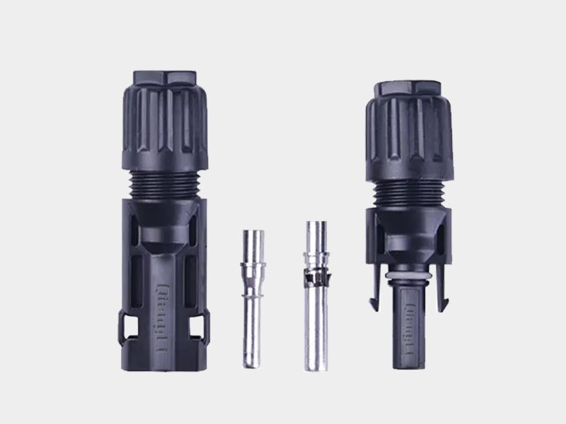
MC4 Connector
Standard: IEC 62852 (DC connectors for PV systems)
Rated Voltage: 1500 V DC
Rated Current: 30 A continuous
Contact Resistance: < 0.5 mΩ (new)
IP Rating: IP67 (mated); IP2X (unmated)
Operating Temperature: −40 °C to +85 °C
Contact Material: Tinned copper alloy (CuSn)
Housing Material: UV-stabilised PPO, halogen-free, UL 94 V-0
Compatible Cable: 2.5 / 4 / 6 / 10 mm² (H1Z2Z2-K solar cable)
Product Overview
MC4 Solar Connector is the universal single-contact plug-and-socket connector for photovoltaic DC wiring. The designation "MC4" stands for Multi-Contact, 4 mm contact pin diameter — the global de-facto standard originated by Stäubli Electrical Connectors (formerly Multi-Contact) and now defined by IEC 62852. Every pair consists of a male plug and a female socket; both lock together with an audible click and can only be separated with a dedicated disconnect tool — preventing accidental disconnection under load.
Rated at 1500 V DC / 30 A and sealed to IP67, MC4 connectors are compatible with all H1Z2Z2-K solar cables from 2.5 mm² to 10 mm² conductor cross-section. The UV-stabilised PPO housing withstands 25+ years of outdoor exposure; the tinned copper alloy contact maintains low contact resistance for the lifetime of the PV system. Our MC4 connectors are TUV Rheinland certified and cross-compatible with connectors from major manufacturers including Stäubli, Amphenol, and Huawei equivalents.
IP67 Weatherproof Seal
Fully dust-tight and protected against temporary water immersion. Connectors remain safe and low-resistance in rain, condensation, and humid rooftop environments for 25+ years.
1500 V DC Rated
Compliant with modern high-voltage PV systems up to 1500 V DC system voltage — the current industry standard for utility-scale and commercial solar projects.
30 A Continuous Current
Rated 30 A continuous at 85 °C connector body temperature, covering the full current output of standard 60/72/144-cell PV modules in all string configurations.
Tool-Required Disconnect
The snap-lock mechanism prevents accidental disconnection under live DC load — a critical safety requirement since DC arcing at PV voltages cannot self-extinguish like AC arcing.
Low Contact Resistance
Tinned copper alloy contact with spring retention maintains <0.5 mΩ contact resistance throughout the connector life — negligible power loss even at maximum current.
Cross-Compatible Design
Mechanically and electrically compatible with IEC 62852 compliant MC4 connectors from Stäubli, Amphenol, Huawei, and equivalents. Works with all standard MC4 disconnect tools.
Technical Specifications
Electrical & Mechanical Parameters
| Standard | IEC 62852 (Connectors for DC-application in photovoltaic systems) |
|---|---|
| Rated Voltage | 1500 V DC (IEC 62852 Class II) |
| Rated Current | 30 A continuous |
| Contact Resistance | < 0.5 mΩ (new); < 1.0 mΩ (after ageing per IEC 62852) |
| Insulation Resistance | > 1000 MΩ (500 V DC test) |
| Dielectric Withstand | 6000 V DC / 1 min (no breakdown) |
| IP Rating | IP67 (mated pair); IP2X (unmated, safety class) |
| Operating Temperature | −40 °C to +85 °C (continuous) |
| Contact Material | Tinned copper alloy (CuSn alloy) |
| Housing Material | UV-stabilised PPO (polyphenylene oxide), halogen-free |
| Cable Entry Range | OD 4.0–8.5 mm (fits H1Z2Z2-K 2.5–10 mm² solar cable) |
| Compatible Cable Cross-Section | 2.5 mm² / 4 mm² / 6 mm² / 10 mm² |
| Crimp Contact Pin Diameter | 4 mm (MC4 standard) |
| Mating Cycles | ≥ 100 (IEC 62852) |
| Locking | Snap-lock; requires MC4 disconnect tool (spanner type) for unmating |
| Flammability | UL 94 V-0 |
| Certification | TUV Rheinland, CE, RoHS |
| Supply | Sold as pairs (1× male + 1× female); bulk bag or box packaging |
Crimp Specification by Cable Size
| Cable Cross-Section (mm²) | Cable OD Range (mm) | Crimp Contact Size | Recommended Crimp Tool | Crimp Force (kN) |
|---|---|---|---|---|
| 2.5 | 4.0 – 6.5 | 2.5 mm² | MC4 crimp tool (hex 3.5 / 4.0) | 2.0 – 2.5 |
| 4 | 5.0 – 7.0 | 4 mm² | MC4 crimp tool (hex 4.0 / 5.0) | 2.5 – 3.0 |
| 6 | 6.0 – 7.5 | 6 mm² | MC4 crimp tool (hex 5.0 / 6.0) | 3.0 – 3.5 |
| 10 | 7.0 – 8.5 | 10 mm² | MC4 crimp tool (hex 6.0 / 8.0) | 3.5 – 4.0 |
Certifications & Standards
How to Install MC4 Connectors
Correct installation is critical — a poorly crimped or improperly sealed MC4 connector is the leading cause of PV system hot spots, arc faults, and fire incidents. Follow this procedure for every termination.
Step-by-Step Crimping & Assembly
- Strip the cable: Remove 18–20 mm of outer jacket (XLPO). Then strip 12–14 mm of insulation to expose the tinned copper conductor. Do not nick or cut conductor strands.
- Slide on the cable gland and locking nut: Thread the back nut and cable gland seal onto the cable before inserting the contact. Once the contact is crimped, the gland cannot be added retroactively.
- Insert conductor into crimp contact: Push the stripped conductor fully into the crimp barrel of the correct-size contact (2.5 / 4 / 6 / 10 mm²). All strands must be inside the barrel — no stray wires outside.
- Crimp with the correct hex die: Use a ratchet MC4 crimp tool with the hex die matching the contact size. Apply full crimp force until the ratchet releases. Verify the contact cannot be pulled out with 50 N hand force.
- Inspect the crimp: The barrel should be uniformly compressed with no cracks, splits, or flared edges. A visual inspection and a pull test (≥ 50 N) confirm a good crimp.
- Insert contact into connector housing: Push the crimped contact into the housing until you hear/feel a click — the secondary lock has engaged. A gentle tug backward confirms retention.
- Tighten the cable gland: Thread and finger-tighten the back nut to compress the seal around the cable jacket. Over-tightening can split the seal; under-tightening compromises IP67.
- Mate the connector pair: Align male and female, push together until the snap-lock clicks. Never force-mate misaligned connectors. Verify mating by a gentle pull — a correctly locked pair will not separate without a disconnect tool.
How to Safely Disconnect MC4 Connectors
- De-energise the string first: Switch off the inverter and confirm DC voltage is zero with a calibrated multimeter. Never disconnect MC4 connectors under live load — DC arcing at PV voltages does not self-extinguish and can cause fire.
- Use the MC4 disconnect tool (spanner type): Insert the forked end of the tool into the locking collar slots on the female connector. Rotate to release the snap-lock tab.
- Pull apart with one hand on each connector: Once unlocked, the connectors slide apart easily. Do not use pliers or force — damaged lock tabs cannot be re-used safely.
Typical Applications
Module String Wiring
Connect PV modules in series strings. Each module junction uses one male + one female MC4 pair.
Residential Rooftop PV
Standard termination for rooftop string wiring from modules to inverter DC input.
Utility-Scale Solar Farms
Thousands of MC4 pairs per MW-class project — reliable, fast, tool-free string connection at scale.
Battery Storage DC Links
Connects PV array output to charge controllers and BESS DC input in off-grid and hybrid systems.
Field Repair & Replacement
Re-terminate damaged pigtails without replacing the full cable run. Restore IP67 with a fresh connector pair.
Portable & Off-Grid Solar
Universal MC4 interface on portable panels, camping kits, boat and RV solar systems worldwide.
Related Products
EN 50618 / TUV certified — 1.5–120 mm², bulk drum supply
Red + black paired — 2.5–16 mm², simplifies string polarity routing
H1Z2Z2-K cable with MC4 connectors factory-crimped — plug-and-play, 0.5–10 m
Request a Quote
Frequently Asked Questions
As a factory, we offer flexible MOQ depending on the cable type. For standard stock items, MOQ is low; for customized specifications, please contact our sales team for a detailed quote.
Yes, Qiangli cables are manufactured in compliance with international standards such as UL, CE, TUV, and VDE. We provide full test reports and certificates upon request.
Absolutely. We have a dedicated R&D team that can customize cable structure, material, color, and printing to meet your specific project needs.
For standard products, lead time is usually 7-15 days. For large-scale project orders or customized products, it typically ranges from 20 to 30 days.
Yes, we provide free samples for most standard cables. You only need to cover the international courier costs. Contact us to arrange your sample shipment.