
Factory-Direct Supply of Certified Wires and Conductors for Diverse Industrial Applications
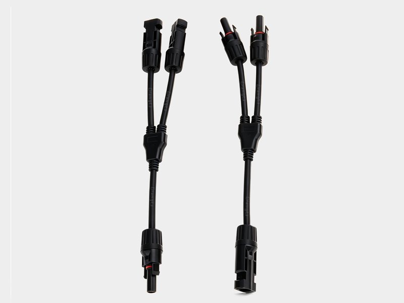
Y-Branch Connector
Standard: IEC 62852
Configuration: Y-shape — 1 input + 2 outputs (1-into-2 distribution)
Rated Voltage: 1500 V DC
Rated Current (per port): 30 A continuous
Max. Input Current: 60 A (input cable must be sized for combined load)
Contact Resistance: < 0.5 mΩ per port
IP Rating: IP67 (all ports mated)
Operating Temperature: −40 °C to +85 °C
Contact Material: Tinned copper alloy (CuSn)
Housing Material: UV-stabilised PPO, halogen-free, UL 94 V-0
Product Overview
Y-Branch MC4 Connector is a three-port MC4-compatible junction connector that splits one DC input into two parallel outputs — the inverse function of the T-Branch. Its Y-shaped body has one input port and two output ports, all within a single IP67 weatherproof housing rated at 1500 V DC. Available in positive and negative versions, a matched Y-Branch pair is used to feed power from a single string or trunk cable to two parallel loads, sub-arrays, or storage inputs — without an additional combiner box or junction enclosure.
While the T-Branch combines two strings into one output (many-to-one), the Y-Branch distributes one source to two destinations (one-to-many). Common use cases include splitting a single inverter DC output to charge two battery banks simultaneously, distributing one trunk cable to two parallel sub-array sections, or feeding one string to two parallel MPPT channels. All three ports use the standard MC4 snap-lock interface, fully compatible with H1Z2Z2-K solar cables and pre-assembled PV leads. Certified to IEC 62852 by TUV Rheinland.
1-into-2 DC Distribution
Splits one DC source into two parallel outputs in a single connector body — no junction box, no terminal blocks, no additional enclosure required on site.
IP67 Fully Weatherproof
All three ports individually sealed to IP67. Withstands direct rain, condensation, and temporary water immersion across the full outdoor installation lifetime.
1500 V DC / 30 A per Port
Each output port rated 30 A. The input port must carry the combined current of both outputs — size the input cable cross-section to the total load current.
Tool-Free MC4 Connection
All ports use standard MC4 snap-lock — plug in and click locked. Only the cable-side crimp contacts require a crimp tool; the Y-Branch body itself needs no tools to assemble.
Matched Positive + Negative Pair
Always installed as a pair: one positive Y-Branch (one female input, two male outputs) and one negative Y-Branch (one male input, two female outputs). Polarity is permanently enforced by the connector gender.
TUV Rheinland Certified
Certified to IEC 62852 — UV ageing, thermal cycling, humidity, and mechanical pull-out tests confirmed. Accepted by EPC contractors and project lenders for 25-year outdoor PV installations.
Technical Specifications
Electrical & Mechanical Parameters
| Standard | IEC 62852 (DC connectors for PV systems) |
|---|---|
| Configuration | Y-shape: 1 input + 2 outputs (1-into-2 distribution) |
| Rated Voltage | 1500 V DC |
| Rated Current (per port) | 30 A continuous |
| Max. Input Current | 60 A (combined load of both outputs; input cable must be sized accordingly) |
| Contact Resistance | < 0.5 mΩ per port (new); < 1.0 mΩ after ageing |
| Insulation Resistance | > 1000 MΩ (500 V DC test) |
| Dielectric Withstand | 6000 V DC / 1 min |
| IP Rating | IP67 (all ports mated) |
| Operating Temperature | −40 °C to +85 °C |
| Contact Material | Tinned copper alloy (CuSn) |
| Housing Material | UV-stabilised PPO, halogen-free, UL 94 V-0 |
| Compatible Cable Cross-Section | 2.5 mm² / 4 mm² / 6 mm² / 10 mm² |
| Cable Entry Range | OD 4.0–8.5 mm per port |
| Port Interface | Standard MC4-compatible snap-lock on all three ports |
| Versions | Positive: 1× female input + 2× male outputs / Negative: 1× male input + 2× female outputs |
| Disconnect | Requires MC4 spanner disconnect tool per port |
| Flammability | UL 94 V-0 |
| Certification | TUV Rheinland, CE, RoHS |
| Supply | Sold as pairs (1× positive + 1× negative Y-Branch) |
Y-Branch vs T-Branch — Quick Comparison
| Feature | Y-Branch | T-Branch |
|---|---|---|
| Function | 1 input → 2 outputs (split / distribute) | 2 inputs → 1 output (combine / parallel) |
| Typical use | One source feeding two loads or sub-arrays | Two strings combining to one inverter input |
| Input port | 1 (carries combined current of both outputs) | 1 output (carries combined current of both inputs) |
| Output ports | 2 (each rated 30 A) | 2 input ports (each rated 30 A) |
| Positive version | 1× female in + 2× male out | 2× female in + 1× male out |
| Negative version | 1× male in + 2× female out | 2× male in + 1× female out |
Certifications & Standards
How to Use the Y-Branch Connector
The Y-Branch distributes one DC source to two parallel destinations. Install one positive Y-Branch and one negative Y-Branch together to form a complete 1-to-2 DC distribution junction.
Wiring Principle
DC source positive → Female input port of positive Y-Branch
Output A positive ← Male output port A of positive Y-Branch → Load / sub-array A DC+
Output B positive ← Male output port B of positive Y-Branch → Load / sub-array B DC+
DC source negative → Male input port of negative Y-Branch
Output A negative ← Female output port A of negative Y-Branch → Load / sub-array A DC−
Output B negative ← Female output port B of negative Y-Branch → Load / sub-array B DC−
Installation Steps
- De-energise the source: Switch off the inverter or disconnect the source string and verify zero DC voltage with a calibrated multimeter before making any connections.
- Identify positive and negative Y-Branches: The positive Y-Branch has one female input and two male outputs. The negative Y-Branch has one male input and two female outputs. Confirm before connecting.
- Connect the source positive cable (red, MC4 male from string/inverter output) into the female input port of the positive Y-Branch until the snap-lock clicks.
- Connect output branch A positive (red cable to load A) into male output port A of the positive Y-Branch. Snap-lock must click fully.
- Connect output branch B positive (red cable to load B) into male output port B. Both output ports must be connected — leave no port open and unsealed.
- Repeat steps 3–5 for the negative Y-Branch using black (negative) cables: source negative into the male input, load A and B negatives into the two female output ports.
- Verify input cable rating: Confirm the source-side cable cross-section is rated for the combined current of both output branches operating simultaneously.
- Inspect and power up: Tug each cable to confirm snap-lock retention. Switch on the source and verify both output branches are receiving expected voltage. Cap any unused port with an MC4 blanking plug.
When NOT to Use a Y-Branch
- Combined output current exceeds 30 A per branch: Each output port is rated 30 A. If either load draws more than 30 A, use a combiner box with appropriately rated terminals.
- More than 2 outputs needed: Daisy-chaining multiple Y-Branches in series is not recommended — use a proper distribution box or combiner for 3+ outputs.
- Loads are significantly unbalanced: If one branch draws much more current than the other, the idle branch may allow reverse current flow. Use fused combiners for unbalanced load scenarios.
Typical Applications
1-to-2 DC Distribution
Split one inverter output or string lead to two parallel loads — no junction box required.
Dual Battery Bank Charging
Distribute one charge controller DC output to two parallel battery banks in off-grid systems.
Split Sub-Array Feed
Feed one trunk cable to two parallel panel sub-sections on split-roof or east-west installations.
Parallel MPPT Input Feed
Connect one string to two parallel MPPT tracker inputs on multi-MPPT inverters for redundancy.
Portable & Off-Grid Solar
Split one panel output to two parallel loads — lighting and USB charger, or two small appliances.
System Testing & Commissioning
Temporarily branch a string to a measurement instrument and the live load simultaneously during commissioning.
Related Products
EN 50618 / TUV certified — 1.5–120 mm², bulk drum supply
Red + black paired — 2.5–16 mm², simplifies string polarity routing
H1Z2Z2-K with MC4 connectors factory-crimped — plug-and-play, 0.5–10 m
Request a Quote
Frequently Asked Questions
As a factory, we offer flexible MOQ depending on the cable type. For standard stock items, MOQ is low; for customized specifications, please contact our sales team for a detailed quote.
Yes, Qiangli cables are manufactured in compliance with international standards such as UL, CE, TUV, and VDE. We provide full test reports and certificates upon request.
Absolutely. We have a dedicated R&D team that can customize cable structure, material, color, and printing to meet your specific project needs.
For standard products, lead time is usually 7-15 days. For large-scale project orders or customized products, it typically ranges from 20 to 30 days.
Yes, we provide free samples for most standard cables. You only need to cover the international courier costs. Contact us to arrange your sample shipment.